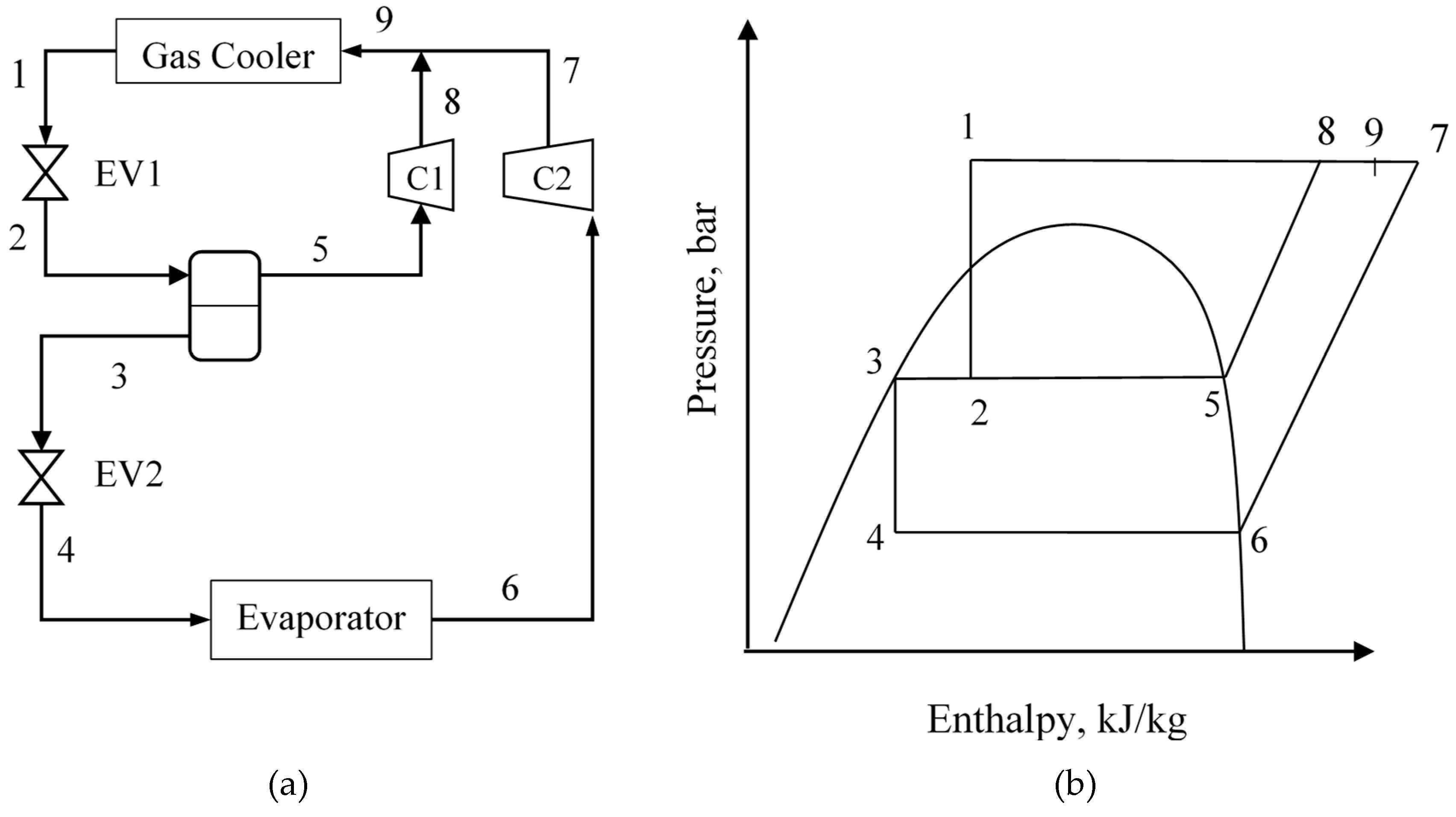

The low side is the low pressure part of the refrigeration system. The function of the receiver is to store the liquid refrigerant to ensure that a constant supply of liquid is available to the evaporator. The sub-cooled liquid then goes into the receiver and is ready to be circulated again. When the vapor leaves the condenser coil, all the vapor would has been condensed and further sub-cooled. The vapor condenses into liquid state as more heat is removed from it. When this happens, the temperature of the vapor drops to the new saturation temperature corresponding to its new pressure. The vapor then flows into the condenser where heat is transferred to the cool air that is drawn into the surface of the condenser coil by the condenser fan. This happens as the heat to supply the latent heat of vaporization passes from the refrigerated space though the walls of the evaporator to the vaporizing liquid. The liquid vaporizes at a constant temperature and pressure in the evaporator coil.


This is so that the saturation temperature of the refrigerant that enters the evaporator will be lower than the refrigerated space.Īs the liquid passes through the flow control, a portion of the liquid vaporizes to reduce the liquid temperature to the evaporating temperature. The liquid high pressure is then reduced to the evaporator pressure as it passes through the flow control. This liquid flows from the receiver through the liquid line to the refrigerant flow control. The receiver is located after the compressor where the high pressure and high temperature liquid refrigerant is stored. The expansion of the liquid refrigerant is handled by the flow control device which can be thermal expansion valve(TXV) or capillary tube. Here are the refrigeration cycle of a direct expansion system. This type of system is also known as the vapor compression systems. A normal valve is used when a cooling only system is needed. The valve used is a reversing valve that reverses the refrigerant flow to enable the heat pump to run cooling or heating. The diagram above shows a cooling cycle of a heat pump DX system.


 0 kommentar(er)
